-
 +86-0571-83175630
-
 [email protected]

 English
  Español
  عربى
عربى 
Thermally Conductive Insulating Coating for TSC Power Modules
Content
- 1 Why the Confusion Between Coatings and TIMs Persists
- 2 Stage One: Natural Cooling in Through-Hole Packages
- 3 Stage Two: Two Decades of Bottom-Side Cooling
- 4 Stage Three: Top-Side Cooling for Wide-Bandgap Devices
- 5 How a Thermally Conductive Insulating Coating Changes the Stack
- 6 What Production-Grade Coatings Look Like Today
- 7 Why the Architecture Keeps Evolving
- 7.1 Does a thermally conductive insulating coating replace thermal grease or pads entirely?
- 7.2 Why did top-side cooling become necessary for SiC and GaN devices?
- 7.3 What is the main reliability advantage of a coating over a ceramic insulating sheet?
- 7.4 Can a thermally conductive insulating coating cover irregular or curved device surfaces?
A thermally conductive insulating coating is a functional insulating base material that provides high-voltage dielectric protection and a flat mounting surface, with thermal conduction as a secondary benefit. Unlike a thermal interface material (TIM), it cannot eliminate interfacial air gaps on its own, so it is applied together with a TIM layer rather than as a standalone replacement.
Why the Confusion Between Coatings and TIMs Persists
Demand for thermal interface materials has climbed sharply alongside the AI computing boom, with reports that even Nvidia is evaluating diamond-based thermal materials for its highest-power chips. Amid this growth, a newer category, thermally conductive insulating coating, has entered the market and is frequently mistaken for a drop-in TIM substitute.
The two materials serve different jobs. A TIM, such as a thermal pad or grease, is a pure interface filler whose core task is removing the air gap between two mating surfaces. A thermally conductive insulating coating is a functional insulating substrate: its core value is high-voltage isolation and a flattened base for the device or heatsink. Once cured, the coating surface still carries microscopic peaks and valleys, so a TIM layer is still required on top of it to achieve efficient system-level heat transfer.
Stage One: Natural Cooling in Through-Hole Packages
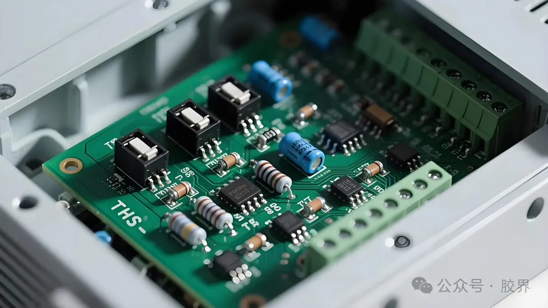
Before surface-mount technology became standard, power devices used through-hole packages such as the TO series. Heat traveled from the chip through a metal leadframe, out through the pins, across the PCB, and finally into an external heatsink.
Thermal interface materials were still primitive at this stage. Engineers relied on simple silicone-based thermal grease filled with ordinary zinc oxide or aluminum oxide particles, mainly for insulation rather than heat spreading. Device power levels were low enough that a TO package thermal resistance of 50 to 80 degrees Celsius per watt was still acceptable, even though thin pin cross-sections created high resistance and left little headroom as currents increased.
Stage Two: Two Decades of Bottom-Side Cooling
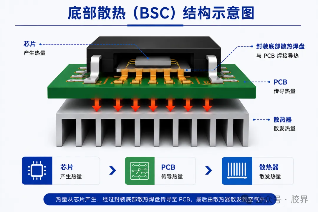
As switching power supplies and motor drives pushed power density higher, the industry shifted to bottom-side cooling (BSC), using the PCB itself as a first-stage heatsink. This architecture dominated power packaging for roughly twenty years across three generations.
Generation 1: Exposed Bottom Pad
Packages like D2PAK and TO-263 brought the drain terminal straight to a large exposed metal pad on the package underside, creating a direct chip-to-PCB thermal path. This pulled the PCB into the cooling system for the first time, though the PCB's own conductivity, roughly 0.3 to 1.5 W/m·K, quickly became the new limiting factor.
Generation 2: Copper Clip Bonding
To cut resistance and heat buildup from thin bonding wires, manufacturers such as Infineon introduced copper clip technology in lines like OptiMOS, replacing wire bonds at the source terminal with a thick copper clip that doubled as a secondary heat path while boosting current capacity.
Generation 3: Package and PCB Co-Design
Later designs paired more compact dual-row packages with multilayer, thick-copper, buried-copper PCBs to squeeze more conductivity out of the board. The PCB's inherent thermal ceiling remained, heat paths grew more circuitous, and large mandatory keep-out zones on the PCB underside worked against miniaturization.
TIM technology matured in step with these packages. Standard thermal grease became ubiquitous, phase change materials entered use as a solid-at-room-temperature option that softens near 45 to 60 degrees Celsius for better surface conformity and conductivity of 5 to 10 W/m·K without pump-out, and thermal pads built on silicone or acrylate bases with alumina or boron nitride fillers reached 6 to 16 W/m·K as filler loading increased.
Stage Three: Top-Side Cooling for Wide-Bandgap Devices
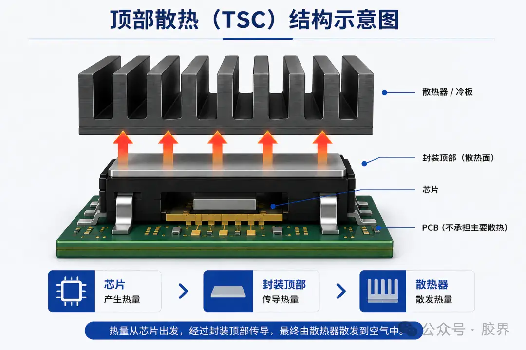
The rise of silicon carbide (SiC) and gallium nitride (GaN) devices, with their higher switching speeds, voltage ratings, and power densities, exposed the limits of bottom-side cooling. The industry's response was top-side cooling (TSC): an exposed metal plate on the package top connects directly to a heatsink or cold plate, bypassing the PCB entirely.
What TSC Improves
- Shorter conduction path lets designers use smaller SiC die for the same thermal budget
- Cooling moves off the PCB, allowing a tighter power loop underneath the device and lower high-frequency EMI
- Package-level creepage distance can be optimized for 800V-class high-voltage platforms
What TSC Complicates
- The device top and the heatsink now need electrical isolation, historically solved with a grease-ceramic-grease sandwich
- Four stacked interfaces in that sandwich accumulate thermal resistance
- Rigid ceramic sheets cannot conform to the small, irregular top surfaces typical of TSC devices, leaving local voids and reliability risk under automotive vibration and thermal cycling
How a Thermally Conductive Insulating Coating Changes the Stack
To simplify this sandwich, the industry developed waterborne epoxy thermally conductive insulating coating as an integrated insulation-plus-conduction material. The goal is to replace one TIM layer and a ceramic insulating sheet with a single coating, producing a new heat path: chip, one TIM layer, top-side thermally conductive insulating coating, then the water-cooled plate or heatsink.
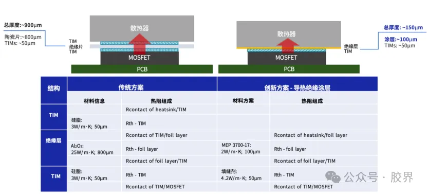
| Attribute | Ceramic Sandwich Stack | Coating Plus TIM Stack |
| Interface layers | Grease, ceramic sheet, grease | Single TIM layer plus coating |
| Total thickness | 800μm or more | 100 to 250μm |
| Bond to heatsink | Physical contact | Chemical bond |
| Brittle cracking risk | Present in ceramic | Avoided with epoxy matrix |
| Irregular top coverage | Limited by rigid sheet | Full coverage via spray coating |
A thermally conductive insulating coating does not replace a TIM. It optimizes the insulation layer so the accompanying TIM can be thinner, more reliable, and better conformed to the interface it fills.
What Production-Grade Coatings Look Like Today
Since 2022, as 800V electric vehicle platforms scaled up, TSC packaging reached mass production maturity alongside waterborne epoxy coating technology. MEPCOAT's MEP 3700 series is one representative product, combining a thermal conductivity of 2 W/m·K with 3,000 to 6,000V of high-voltage insulation, strong interfacial adhesion, and automotive-grade reliability in a single layer.
Beyond automotive-grade validation across thousands of temperature cycles and 96 hours of salt spray exposure, these coatings support precise thickness control: a single pass can lay down as little as five microns, or successive spray-and-cure cycles can build up to a target thickness while avoiding the bubbles and voids that would otherwise hurt insulation yield.
Why the Architecture Keeps Evolving
Every stage of this history, from through-hole natural cooling to two decades of bottom-side cooling to today's top-side cooling with thermally conductive insulating coating, follows the same underlying logic: shorten the heat path, cut the number of interfaces, balance insulation against heat dissipation, and adapt to smaller devices. As SiC adoption spreads and vehicle voltage platforms push past 800V, the limits of multilayer pads and ceramic sheets become harder to ignore, and coating-plus-TIM pairing is emerging as the practical way forward for compact, high-power-density electric drive units.
Does a thermally conductive insulating coating replace thermal grease or pads entirely?
No. A coating still leaves microscopic surface irregularities after curing, so a TIM such as thermal grease or a thermal pad remains necessary to fill the final interfacial air gap.
Why did top-side cooling become necessary for SiC and GaN devices?
Wide-bandgap devices switch faster, run at higher voltage, and pack more power into a smaller footprint than legacy silicon parts, and bottom-side cooling through the PCB could no longer keep pace with the heat these devices generate.
What is the main reliability advantage of a coating over a ceramic insulating sheet?
The coating forms a chemical bond to the heatsink surface rather than relying on physical contact, and its epoxy matrix has no ceramic brittle-cracking risk, so it holds up better under automotive-grade vibration and thermal cycling.
Can a thermally conductive insulating coating cover irregular or curved device surfaces?
Yes. Because it is applied by spray rather than as a pre-cut sheet, it can fully wrap curved surfaces, grooves, and small top-side cooling device geometries in a single process step.
CONTACT DETAILS
- Address:No. 241, Yaojiafan, Zhangpanqiao, Shushan Street, Xiaoshan District, Hangzhou City, Zhejiang Province, China
- TEL:+86-0571-83175630
- Phone:+86-13336160217
- Email:[email protected]
- WeChat/WhatsApp:+86-18058115265
PRODUCTS
NEWS CENTER
MOBILE TERMINAL
Copyright© Zhejiang Geruite Packaging Materials Co., Ltd. All Rights Reserved.
Privacy Wholesale industrial packaging tape Manufacturers